×
- Hello
- Login or Register
- Quick Links
- Live Chat
- Track Order
- Parts Availability
- RMA
- Help Center
- Contact Us
- Shop for
- Mitsubishi Parts
My Garage
My Account
Cart
Genuine Mitsubishi Galant Relay
Wire Relay- Select Vehicle by Model
- Select Vehicle by VIN
Select Vehicle by Model
orMake
Model
Year
Select Vehicle by VIN
For the most accurate results, select vehicle by your VIN (Vehicle Identification Number).
Part Type
Select Part Type
14 Relays found

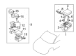
Mitsubishi Galant Horn Relay Part Number: 8627A030
$43.69 MSRP: $60.68You Save: $16.99 (28%)Ships in 1-2 Business Days
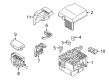
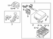
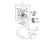
Mitsubishi Galant Relay Box Cover Part Number: MR502417
$5.80 MSRP: $7.56You Save: $1.76 (24%)Ships in 1-2 Business Days
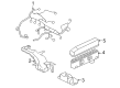
Mitsubishi Galant Fusible Link Pink Part Number: MU840031
$7.01 MSRP: $9.13You Save: $2.12 (24%)Ships in 1-2 Business Days
Mitsubishi Galant Fusible Link Green Part Number: MU840032
$7.36 MSRP: $9.59You Save: $2.23 (24%)Ships in 1-2 Business DaysMitsubishi Galant Fusible Link Purple Part Number: MU840030
$7.73 MSRP: $10.07You Save: $2.34 (24%)Ships in 1-2 Business Days
Mitsubishi Galant Horn Relay Part Number: MR515994
$13.04 MSRP: $16.97You Save: $3.93 (24%)Ships in 1-2 Business Days
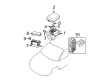
Mitsubishi Galant Relay Box Part Number: MR986305
$14.48 MSRP: $18.85You Save: $4.37 (24%)Ships in 1-2 Business Days
Mitsubishi Galant Fusible Link Green Part Number: MU840016
$14.73 MSRP: $19.17You Save: $4.44 (24%)Ships in 1-2 Business Days
Mitsubishi Galant Horn Relay Part Number: 8627A008
$15.32 MSRP: $19.95You Save: $4.63 (24%)Ships in 1-2 Business Days
Mitsubishi Galant Relay Box Part Number: MR502415
$26.16 MSRP: $34.07You Save: $7.91 (24%)Ships in 1-2 Business Days
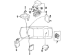
Mitsubishi Galant Starter Relay Part Number: MR524999
$47.03 MSRP: $65.32You Save: $18.29 (28%)Ships in 1-2 Business Days
Mitsubishi Galant ECM Relay Part Number: MD119202
$95.27 MSRP: $132.32You Save: $37.05 (28%)Ships in 1-2 Business Days
Mitsubishi Galant ECM Relay Part Number: MR312504
$34.34 MSRP: $45.07You Save: $10.73 (24%)Ships in 1-2 Business Days
Mitsubishi Galant Starter Relay Part Number: MR301971
$38.23 MSRP: $50.16You Save: $11.93 (24%)Ships in 1-2 Business Days
Mitsubishi Galant Relay
OEM Relay can boast superior quality and long-term durability. Each part meets strict factory specs and passes careful checks in production. So you'll get Relay with long-lasting strength and an exact fit. If you need OEM Mitsubishi Galant Relay, the online store is the ideal place. The store carry a wide range of genuine Mitsubishi Galant parts at the highly competitive prices. You'll enjoy a simple and no-hassle shopping experience. You'll get unbeatable prices and fast delivery service. You'll get the manufacturer's warranty and a straightforward return policy. Shop with confidence and keep your car in top condition.
Mitsubishi Galant Relay Parts Questions & Experts Answers
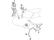
- Q: What are the functions and testing procedures for relays in electrical systems on Mitsubishi Galant?A:Electric devices, like the fuel injection system, Horns, starter, and fog lamps, utilize relays to send electric signals to the parts in the vehicle. A low-power control circuit is used in relays to open or close a high-power electrical circuit. If the relay of the associated component fails, it may not function at all. Most relays are located in the fuse/relay box of the engine compartment. Some specialized relays are located above the interior fuse box in the dash. If a malfunctioning relay is suspected of causing the problem, it can be taken out and tested. A specific procedure exists to test a relay, or a dealer service department or repair shop can do it. If defective, relay must be replaced by a unit. The relays that you will mostly find are commonly called ISO relays. Their terminal number indicates their circuit connection and function. Two terminals are for the relay control circuit and are connected to the terminals of the relay coil. The other terminals are of the power circuit. When the coil is energized, a magnetic field is created which closes the larger contacts of the power circuit to supply power to the loads. In most cases, terminals 85 and 86 will designate the control circuit. If there is a diode, terminal 86 needs to connect to battery positive voltage. Meanwhile, if there's a resistor, terminals 85 and 86 can get connected in either direction. Terminal 30 typically connects to the source of battery voltage for circuit loads, while terminal 87 connects to the powered component. To test the relay, an ohmmeter can be used to check continuity through the relay control coil, making sure to connect the meter according to the marked polarity and reverse the leads for a second check. In case there is a resistor, the resistance will be the same both ways but with a diode the resistance will be more one way. If infinite resistance occurs in both directions, relay replacement is necessary. Once the Relay has been removed, continuity must be checked between circuit power terminals. Always ensure that there is no continuity between terminal 30 and 87 when relay is de-energized. If two jumper wires are used to connect terminal 86 to the positive battery terminal, and terminal 85 to ground, the relay should click and then continuity should be present between terminals 30 and 87. If the relay fails any of these tests, it should be replaced.

Related Mitsubishi Galant Parts
 Mitsubishi Galant Fuel Pump Relay
 Mitsubishi Galant Starter Relay
 Mitsubishi Galant ABS Relay
 Mitsubishi Galant Cruise Control Switch
 Mitsubishi Galant Flasher Relay
 Mitsubishi Galant Fuse
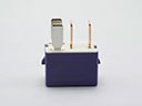 Mitsubishi Galant Ignition Relay
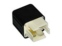 Mitsubishi Galant Overload Relay
 Mitsubishi Galant Relay Block
 Mitsubishi Galant Relay Boxes
 Mitsubishi Galant Speed Sensor
 Mitsubishi Galant Temperature Sender