×
- Hello
- Login or Register
- Quick Links
- Live Chat
- Track Order
- Parts Availability
- RMA
- Help Center
- Contact Us
- Shop for
- Mitsubishi Parts
My Garage
My Account
Cart
Genuine Mitsubishi Lancer Front Cross-Member
Front Engine Cross Member- Select Vehicle by Model
- Select Vehicle by VIN
Select Vehicle by Model
orMake
Model
Year
Select Vehicle by VIN
For the most accurate results, select vehicle by your VIN (Vehicle Identification Number).
27 Front Cross-Members found

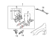
Mitsubishi Lancer Inner Panel, Passenger Side Part Number: 5253B340
$243.65 MSRP: $344.13You Save: $100.48 (30%)Ships in 1-2 Business Days
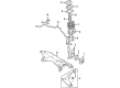
Mitsubishi Lancer Inner Rail, Passenger Side Part Number: 5220D148
$261.71 MSRP: $369.65You Save: $107.94 (30%)Ships in 1-2 Business DaysMitsubishi Lancer Inner Rail, Driver Side Part Number: 5220C483
$266.95 MSRP: $377.05You Save: $110.10 (30%)Ships in 1-2 Business DaysMitsubishi Lancer Inner Rail, Passenger Side Part Number: 5220C484
$269.57 MSRP: $380.75You Save: $111.18 (30%)Ships in 1-2 Business Days
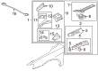
Mitsubishi Lancer Crossmember Part Number: 5230B600
$363.40 MSRP: $513.28You Save: $149.88 (30%)Ships in 1-2 Business Days
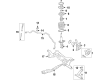
Mitsubishi Lancer Suspension Crossmember Part Number: 4000A428
$391.08 MSRP: $552.37You Save: $161.29 (30%)Ships in 1-2 Business Days
Mitsubishi Lancer Sidemember Assembly, Passenger Side Part Number: 5253B338
$439.03 MSRP: $620.10You Save: $181.07 (30%)Ships in 1-2 Business Days
Mitsubishi Lancer Suspension Crossmember Part Number: MR510285
$455.63 MSRP: $643.56You Save: $187.93 (30%)Ships in 1-2 Business Days
Mitsubishi Lancer Lower Rail Assembly, Passenger Side Part Number: 5220D728
$481.68 MSRP: $680.33You Save: $198.65 (30%)Ships in 1-2 Business Days
Mitsubishi Lancer Lower Rail Assembly, Driver Side Part Number: 5220D695
$486.40 MSRP: $687.00You Save: $200.60 (30%)Ships in 1-2 Business DaysMitsubishi Lancer Lower Rail Assembly, Passenger Side Part Number: 5220D694
$491.99 MSRP: $694.90You Save: $202.91 (30%)Ships in 1-2 Business DaysMitsubishi Lancer Lower Rail Assembly, Driver Side Part Number: 5220D727
$529.57 MSRP: $747.98You Save: $218.41 (30%)Ships in 1-2 Business Days
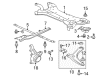
Mitsubishi Lancer Suspension Crossmember Part Number: 4000A124
$544.32 MSRP: $768.81You Save: $224.49 (30%)Ships in 1-2 Business Days
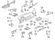
Mitsubishi Lancer Reinforcement Plate Part Number: 5253D120
$73.28 MSRP: $101.78You Save: $28.50 (28%)Ships in 1-2 Business Days
Mitsubishi Lancer Upper Crossmember, Passenger Side Part Number: 5253D112
$117.64 MSRP: $163.38You Save: $45.74 (28%)Ships in 1-2 Business DaysMitsubishi Lancer Upper Crossmember, Driver Side Part Number: 5253D111
$118.78 MSRP: $164.97You Save: $46.19 (28%)Ships in 1-2 Business Days
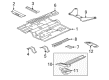
Mitsubishi Lancer Floor Crossmember Part Number: 5253D231
$127.94 MSRP: $173.36You Save: $45.42 (27%)Ships in 1-2 Business Days
Mitsubishi Lancer Rail Support, Driver Side Part Number: 5220C493
$128.56 MSRP: $174.20You Save: $45.64 (27%)Ships in 1-2 Business Days
Mitsubishi Lancer Outer Rail, Driver Side Part Number: 5220C857
$129.88 MSRP: $175.98You Save: $46.10 (27%)Ships in 1-2 Business Days
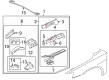
Mitsubishi Lancer Outer Panel, Passenger Side Part Number: MR592574
$131.65 MSRP: $178.38You Save: $46.73 (27%)Ships in 1-2 Business Days
| Page 1 of 2 |Next >
1-20 of 27 Results
Mitsubishi Lancer Front Cross-Member
OEM Front Cross-Member can boast superior quality and long-term durability. Each part meets strict factory specs and passes careful checks in production. So you'll get Front Cross-Member with long-lasting strength and an exact fit. If you need OEM Mitsubishi Lancer Front Cross-Member, the online store is the ideal place. The store carry a wide range of genuine Mitsubishi Lancer parts at the highly competitive prices. You'll enjoy a simple and no-hassle shopping experience. You'll get unbeatable prices and fast delivery service. You'll get the manufacturer's warranty and a straightforward return policy. Shop with confidence and keep your car in top condition.
Mitsubishi Lancer Front Cross-Member Parts Questions & Experts Answers
- Q: How to remove and install the steering gear assembly on the Front Cross-Member with an airbag on Mitsubishi Lancer?A:To take off and install, First, disconnect the negative battery terminal on airbag-equipped models (and wait at least 60 seconds to disable it). Make sure the ignition key is removed and steering wheel is locked straight ahead. When removing the steering gear assembly from vehicles with an airbag, engage the steering lock. The steering cannot then be moved further than its normal locked position, otherwise the Clock Spring will be damaged. For CG and CH model vehicles, quickly dry paint the relationship between the intermediate shaft and steering gear, and remove the pinch bolt and washer to separate them. Securely elevate the front of the vehicle on jack stands and detach the front tires. Next, extract both sides' stabiliser bar link nut and bolt and their respective washers, bushes and spacer tube and note the order of removal. Remove the bolts retaining the control arm rear pivot bush brackets to the crossmember and withdraw these brackets. Lower the control arms, using wire to hold them in position, to avoid strain on the ball joints. Loosen the castellated nut that secures the tie rod end to the Steering Knuckle on both sides. Note that on some models there is a self-locking nut in place of the castellated nut and it must be discarded when removed. Remove the tie rod ends from the steering knuckles by means of a ball joint separator or by striking the knuckle with a hammer. Detach and remove the bolts securing the steering gear to the crossmember. Pull the steering gear away and suspend it with wire, if possible. On models CG and CH, the steering gear is lowered with the crossmember. Detach the engine pipe along with the front and rear engine mounting through bolts. Remove the bolts retaining the centre member and withdraw it while someone steadies the engine. Lower the crossmember; manoeuvre across and out from under the vehicle. For CG and CH models, disconnect hydraulic lines from the power steering gear before lowering the crossmember with the steering gear. Putting the installation back on the car is basically the reverse of the removal process. Follow the steps outlined and remember to check the crossmember for damage and renew accordingly. Check stabiliser bar bushes, which are on the bracket and bolts, and tighten correctly. During mounting, don't cause damage of the steering gear boots. For CE models, the steering gear retaining bolts should be torque to situation. For CG and CH Models firstly mount the steering gear properly. Then raise the crossmember and guide the intermediate shaft into the firewall cavity. When the gear is high enough fit and tighten the power steering hoses. Tighten the control arm rear pivot bush bracket bolts then install front pivot bolt loosely. Install stabiliser bar link components in noted order and tighten retaining nut. Attach the center member, tightening the retaining bolts, then take the front wheels back on and lower the vehicle, bouncing the front to stabilise suspension and lightly settling the bushes making sure to then tighten the front control arm pivot bolt, and finally securely connect the battery terminal on models with airbag.

Related Mitsubishi Lancer Parts
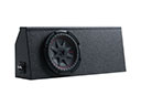 Mitsubishi Lancer Subwoofer
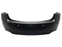 Mitsubishi Lancer Bumper Cover
 Mitsubishi Lancer Door Seal
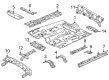
 Mitsubishi Lancer Floor Pan
 Mitsubishi Lancer Interior Door Handle
 Mitsubishi Lancer Mirror Switch
 Mitsubishi Lancer Rear Crossmember
 Mitsubishi Lancer Seat Cushion
 Mitsubishi Lancer Seat Switch Panel
 Mitsubishi Lancer Trunk Lid Latch
 Mitsubishi Lancer Weather Strip
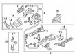
 Mitsubishi Lancer Wheelhouse